
Problem Statement
The objective of this project was to design and program a two-axis machine that could be controlled using potentiometer inputs. The machine needed to be capable of precise movements in both the X and Y axes, allowing for fast and accurate positioning and operation. The challenge was to create a system that was not only functional but also efficient and user-friendly.
Design Process
There were three main components to this project. Each component required a mix of circuitry and software design to ensure the system worked seamlessly together. The first component was to define motor behaviour to handle limit switch triggering. A key feature that had to be considered in design was that since the machine could potentially trigger both switches at the same time. Therefore the system must be able to handle simultaneous triggers and move the motors back to a safe position. To implement this type of algorithm, software interrupts were used to catch the limit switch triggers.
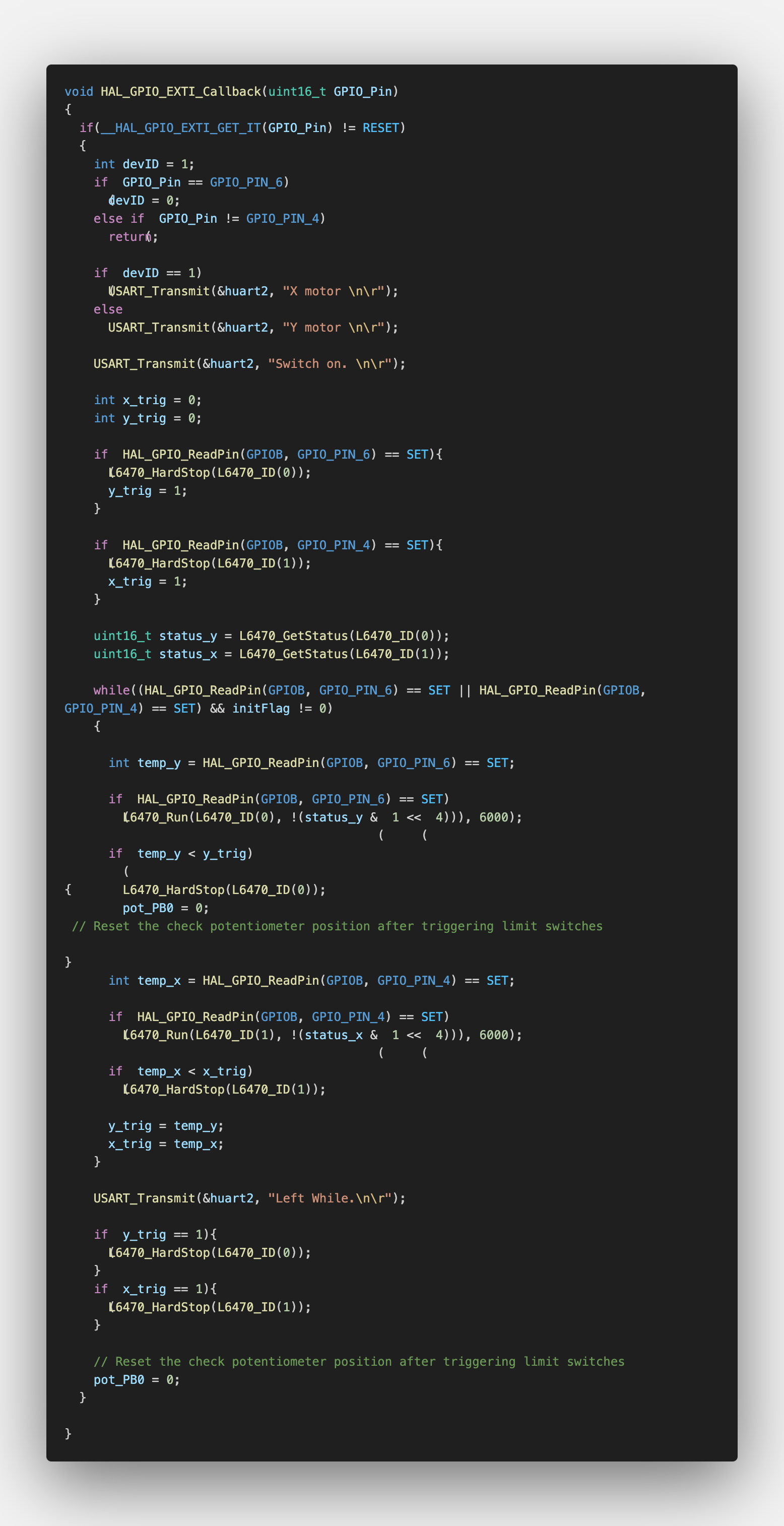
Limit Switch Interrupt Code
The next component was to implement ADC reading of potentiometer inputs to control the position of the motors. Once the code was implemented, it was then cross referenced to voltage readings from the potentiometer to verify accurate readings. The ADC readings were then mapped to the motor speed and direction. A deadband was also implemented to prevent the motors from moving when the potentiometer was in the center position. This was done to prevent the motors from constantly moving when the potentiometer was not being adjusted. Furthermore, the range of values usable for controlling the motors was made dynamic accross the range of the potentiometer such that once the system is started, it is not a requirement for the potentiometer to be set inside the deadband, allowing easier usage.

ADC Input Mapping
ADC input to system output
The last major component was to put everything together and ensure the system worked with the two-axis machine. This involved testing the system and making adjustments to the code and speed values as necessary. The logic for this portion can be seen in the appendix section below.
Final Design
The finished project was evaluated based on the percision of the movement of the two-axis machine to be able to go to a set target and the time it took to get there. Both of these criteria were found to be completed and recieved full marks.
Horizontal movement charactersed by potentiometer input
Future Steps
- •Implement a second ADC for simultaneous movement in the x and y direction
Appendix
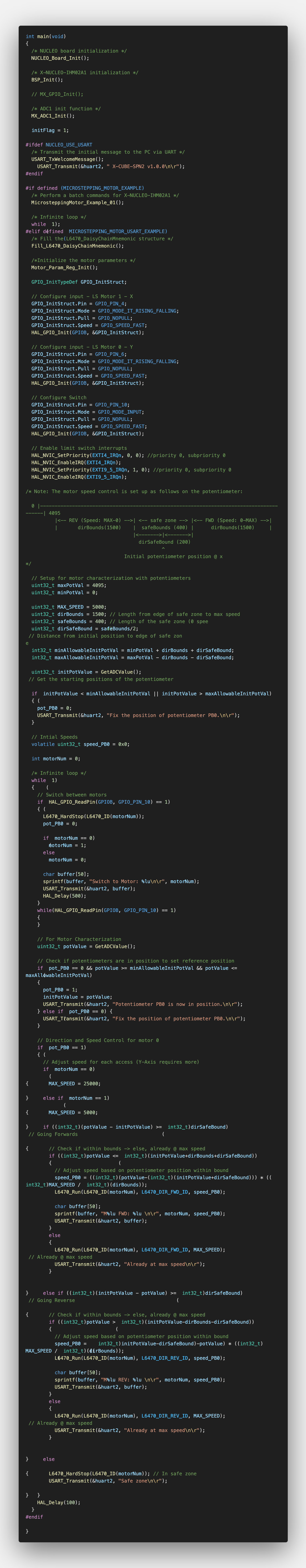
Main System Code